Mechanical Engineering
Nuclear Energy – Current Storage of Radioactive Waste
Domestic Refrigerator Parts and their Working
The domestic refrigerator is one found in almost all the homes for storing food, vegetables, fruits, beverages, and much more. This article describes the important parts of the domestic refrigerator and also their working.
Parts of the Domestic Refrigerator and how they Work
The domestic refrigerator is one found in almost all the homes for storing food, vegetables, fruits, beverages, and much more. This article describes the important parts of the domestic refrigerator and also their working. The parts of domestic refrigerator can be categorized into two categories: internal and external. Let see these in details along with their images.
Parts of the Domestic Refrigerator
Internal Parts of the Domestic Refrigerator
The internal parts of the refrigerator are ones that carry out actual working of the refrigerator. Some of the internal parts are located at the back of the refrigerator, and some inside the main compartment of the refrigerator. Some internal parts of the domestic refrigerator are (please refer the figure above):


1) Refrigerant: The refrigerant flows through all the internal parts of the refrigerator. It is the refrigerant that carries out the cooling effect in the evaporator. It absorbs the heat from the substance to be cooled in the evaporator (chiller or freezer) and throws it to the atmosphere via condenser. The refrigerant keeps on recirculating through all the internal parts of the refrigerator in cycle.
2) Compressor: The compressor is located at the back of the refrigerator and in the bottom area. The compressor sucks the refrigerant from the evaporator and discharges it at high pressure and temperature. The compressor is driven by the electric motor and it is the major power consuming devise of the refrigerator.
3) Condenser: The condenser is the thin coil of copper tubing located at the back of the refrigerator. The refrigerant from the compressor enters the condenser where it is cooled by the atmospheric air thus losing heat absorbed by it in the evaporator and the compressor. To increase the heat transfer rate of the condenser, it is finned externally.
4) Expansive valve or the capillary: The refrigerant leaving the condenser enters the expansion devise, which is the capillary tube in case of the domestic refrigerators. The capillary is the thin copper tubing made up of number of turns of the copper coil. When the refrigerant is passed through the capillary its pressure and temperature drops down suddenly.
5) Evaporator or chiller or freezer: The refrigerant at very low pressure and temperature enters the evaporator or the freezer. The evaporator is the heat exchanger made up of several turns of copper or aluminum tubing. In domestic refrigerators the plate types of evaporator is used as shown in the figure above. The refrigerant absorbs the heat from the substance to be cooled in the evaporator, gets evaporated and it then sucked by the compressor. This cycle keeps on repeating.
6) Temperature control devise or thermostat: To control the temperature inside the refrigerator there is thermostat, whose sensor is connected to the evaporator. The thermostat setting can be done by the round knob inside the refrigerator compartment. When the set temperature is reached inside the refrigerator the thermostat stops the electric supply to the compressor and compressor stops and when the temperature falls below certain level it restarts the supply to the compressor.
7) Defrost system: The defrost system of the refrigerator helps removing the excess ice from the surface of the evaporator. The defrost system can be operated manually by the thermostat button or there is automatic system comprising of the electric heater and the timer.
Those were the some internal parts of the domestic refrigerator; now let us see the external parts of the refrigerator.
Read Full Post | Make a Comment ( None so far )Steps Required to Perform a Finite Element Analysis
The finite element analysis (FEA) or finite element method (FEM) or computer aided engineering (CAE) is used widely. What is FEA? How CAE works? The article will discuss these all using a flow chart for a typical finite element analysis.
What is Finite Element Analysis?
The finite element analysis (FEA) or FEM is a problem solving approach for the practical (engineering)
problems. The problems are first converted to matrix and partial differential equation forms. Eventually the partial differential and integral equations are being solved to reach the solution of the problem. The volume of the equations to be solved is usually so large that arriving solution without using computer is practically impossible. And, that’s why the need of different FEA packages is felt. There are many FEA packages available for different applications. Some popular FEA packages are Pro Mechanica, Ansys, Nastran, and Gambit etc.
Flow Chart for Finite Element Analysis
Typically a complete finite element analysis flow chart should have the steps, for the shake of easy discussions I am writing the steps in bullet points form instead of flow chart form:
•Create 3D CAD Model: Use any of the 3D CAD modeling tools like ProE, Catia, and solid Edge etc. for creating the 3D geometry of the part/assembly of which you want to perform FEA.
•Clean Up the 3D CAD Model: Some features of the 3D CAD geometry may not be that important for the FEA but increase the complexity of meshing drastically; you need to remove those features of the CAD model. For example, if you need to analyze the deflection of the below bar
You better remove the rounds in order to avoid complexity while meshing.
•Save the 3D CAD Geometry in Neutral Format: Save the 3D CAD geometry in neutral format like IGES, STEP etc. Though some of the FEA packages allow importing the CAD geometry directly from some of the 3D CAD packages. For example, the ProE geometry can be directly imported to Ansys.•Importing 3D CAD geometry to FEA Package: Start the FEA package and import the CAD geometry into the FEA package.•Defining Material Properties: You need to tell the FEA package which material you are using for the part. By this process you have to tell modulus of elasticity, poissions ratio and all other necessary properties require for the FEA.•Meshing: Meshing is a critical operation in FEA. In this operation, the CAD geometry is divided into large numbers of small pieces. The small pieces are called mesh. The analysis accuracy and duration depends on the mesh size and orientations. With the increase in mesh size, the finite element analysis speed increase but the accuracy decrease.
•Defining Boundary Condition: You have to tell the FEA package where you want to apply loads and where you want to rest the part/assemble (constraints). •Solve: In this step you tell the FEA package to solve the problem for the defined material properties, boundary conditions and mesh size.•Post Processing: You view the results of the solution in this step. The result can be viewed in various formats: graph, value, animation etc.
Conclusion
The flow chart for finite element analysis (FEA) or FEM or CAE discussed here is typical overview of a FEA. After viewing the results, all or some of the steps may be performed again in order to get the desired result.
Read Full Post | Make a Comment ( None so far )Welding Inspection Methods Using Non Destructive Testing (NDT) Techniques
Welding is a well established process of joining metals together, and a great advancement on riveting. However, some welds failed when put under load, prompting a more thorough method of inspection of welded joints Nowadays there are various techniquesfor non-destructive testing of welds (NDT)
Introduction to Nondestructive Testing of Welding.
When I served my time in Harland and Wolff shipyard in Belfast in the 1960’s, welding had thankfully taken over from riveting. My old next door neighbour had been a riveter on the Titanic and was stone deaf due to the constant hammering of the pneumatic equipment used in those days.
Today most shipyards fabricate large components of hull and deck plates welding them together using automatic welding techniques, which are very efficient and reliable. However, due to stringent regulations set by the various authorities these welds require inspection which nowadays consists of nondestructive testing, known as NDT. There are various types of NDT which allow ferrous and nonferrous welding to be inspected for cracks or other flaws.
This is an article on welding inspection and covers the different methods employed in engineering. We begin by examining some pertinent welding techniques, following on with the methods of NDT.
Welding Techniques used in Marine and Petro-chemical Industries
Before we examine the different types of NDT, it will be worthwhile to give a brief overview of welding alloys of lined pipe and the requirements for pre- and post-welding heat treatment.
In the offshore hydrocarbon and petrochemical industry, there are many different alloys used in pipe fabrication which require specialist welding using Tungsten Inert Gas (TIG) welding that uses an inert gas to shield the weld area from air contact. The gas is supplied through the welding nozzle which holds a tungsten rod. The rod fuses the edges of the two components; a filler rod can also be used if required.
Metal Inert Gas (MIG) welding also uses gas shielding, but in this process as well as supplying gas, the nozzle also supplies a filler rod continuously, which is used to weld the two metals together.
Pre- and post-weld heat treatment
In some heavy-wall pipe and structural components, where metal arc welding is used, heat pads are applied to each side of weld area to relieve any stresses in the metals before welding. This is repeated immediately after welding is completed, the timing and temperatures involved in the heat treatment being calculated and controlled by the welding engineer and his supervisors.
Categories of Non-destructive Testing
The different types of non-destructive testing used to inspect welding are shown below:
•Radiographic Inspection (Graphs)
•Magnetic Particle Inspection(MPI)
•Ultrasonic Testing (UT)
•Dye Penetration (Dye Pen)
Description and Application of Non Destructive Testing Methods
Radiographic Inspection (Graphs)
This is carried out where the welded components require a very critical inspection technique due to their application.
Shielding from x-ray and gamma-ray radiation is a strict requirement; this can be of a portable means or the components can be brought to a specialised building to be x-rayed. In my old offshore construction yard, radiography was carried out during the dead hours between shifts, when a visible and audio alarm would howl continuously to warn against entrance to the assembly buildings.
Anyway, the relative components are exposed to the radioactive source from which a radiograph is produced. This will show any irregularities in the welding when checked by an experienced radiograph interpreter.
Magnetic Particle Inspection (MPI)
The welded area is coated with a magnetic flux containing iron ferrous particles. An electric yoke magnet is placed across the flux producing a visible magnetic field. Any surface cracks or weld irregularities will become evident by the accumulation of the flux due to the forming of a new magnetic pole each side of the crack. This is a very inexpensive and quick method of weld inspection, however it is only used to check fillet welds for surface imperfections, and of course can only be used on ferrous metals.Ultrasonic Testing (UT)
This method can detect surface and internal irregularities in ferrous and non-ferrous metal welding.
It operates by transmitting high frequency pulsing sound waves through the weld, the results being transmitted to a monitor as a trace. If the pulse comes in contact with an irregularity in the weld, the waves are sent back to the transmitter and show up on the monitor screen. The defect can be placed very accurately, but it requires an experienced operator to interpret the tracings on the monitor.
Ultrasonic Testing (UT)
This method can detect surface and internal irregularities in ferrous and non-ferrous metal welding.
It operates by transmitting high frequency pulsing sound waves through the weld, the results being transmitted to a monitor as a trace. If the pulse comes in contact with an irregularity in the weld, the waves are sent back to the transmitter and show up on the monitor screen. The defect can be placed very accurately, but it requires an experienced operator to interpret the tracings on the monitor.
Dye Penetration (Dye Pen)
This system operates on a capillary action principle where a fluid in the form of a florescent or nonflorescent dye is applied to a weld surface.
Once the fluid has been given time to penetrate the surface, (between 15 and 30 minutes) the excess is wiped away and a developing fluid applied. The developer draws fluid out from any flaws and when viewed under a UV or white light, imperfections in the weld become visible.
Read Full Post | Make a Comment ( None so far )How Does CAD Works?
What is Computer Aided Design?
The CAD or the computer aided design process is the enrichment of the traditional manual design process by using computer software and hardware extensively. By using computer the whole design process becomes much faster and robust.
The output of a computer aided design process typically is 2D and/or 3D geometry like curves, surfaces and solids. But often the CAD geometry also contains data like material properties, dimensions, tolerance and manufacturing process specific information.
A typical computer aided design process has the following steps:
•Conceptual system design: Initially, a very rough CAD model of the system is being created without considering the strict dimension control. The main purpose here is just to visualize the product idea.
•Freezing the concept: By reviewing the conceptual system the concept is being frozen. And thus the system level assembly is being finalized.
•Detail component design: The detailed CAD geometry of the individual components is then created with appropriate dimensions and tolerances.
•PDM: Product data management is the database for the CAD geometry and the related documents. In simple term, PDM helps systematic access and revisions of CAD data.
•CAE: The detailed CAD geometry is then used as input for computer aided engineering (CAE) or finite element analysis (FEA) to know whether the geometry will sustain the loading condition or not, if not then required modification is done for the CAD geometry and so on.
•CAM: Once the CAD geometry passed FEA, it then used as input for the computer aided manufacturing for generating NC codes. This NC codes are fed to the CNC machines for manufacturing the components.
How Does CAD Work?
•A CAD software package and sometimes a graphics card must be installed there in your computer for a typical CAD system to work.
•The heart of a CAD software package is its graphics kernel.
•Another important part of the CAD packages is the GUI. The GUI is used for getting user input and displaying the CAD geometry.
•Most of the times, the mouse and the key boards are used as input devices however, the little unknown devices like: tracker ball, digitizer etc are also used sometimes.
•As shown in the above picture, the input from the input devices go to GUI, the GUI then send the input to the graphics kernel in suitable form. The graphics kernel generates the geometric entities and signals the graphics card to display it through the GUI. This is the explanation of the working of a CAD system in a simplest form.
Conclusion
The basic difference between the CAD package and the other software package is that the CAD package has to handle large amount of graphics data and thus the graphics kernel explained in “How does CAD Works?” section is very important. The computer aided design process dicussed under the “What is computer aided design?” section are the outline of the process and may vary from situation to situation.
Read Full Post | Make a Comment ( None so far )Shell and Tube Heat Exchanger Design
Introduction
 Instead of simply one pipe inside another, as for a double pipe heat exchanger, a shell and tube heatexchanger uses multiple tubes in a bundle inside of a ‘shell’. This gives a more compact heat exchanger for a given heat transfer area, but the flow patterns are somewhat more complicated for a shell and tube heat exchanger. The diagram at the left shows the general configuration. Some of the shell and tube heat exchanger options that affect the flow pattern are U-tube or straight tube and how many passes (tube side). The shell side flow pattern is determined by baffles as shown in the diagrams.
A straight tube shell and tube heat exchanger has a tube sheet and a plenum at both ends as shown in the lower two diagrams. The straight tube heat exchanger shown at the right has one tube pass and the one on the left has two tube passes.
Shell and Tube Heat Exchanger Design
The required heat transfer surface area for a shell and tube heat exchanger design is typically found from the basic heat exchanger equation: Q = UA ΔTlm, where:
Q = rate of heat transfer between the two heat exchanger fluids, Btu/hr,
U = overall heat transfer coefficient, BTU/hr-ft2-oF,
A = heat transfer surface area, ft2,
ΔTlm = log mean temperature difference in oF, calculated from the inlet and outlet temperatures of the two fluids.
The basic heat exchanger equation, and the above parameters, are discussed in ‘Fundamentals of Heat Exchanger Design’. An example calculation with the basic heat transfer equation is given in ‘Preliminary Heat Exchanger Design Example’.
If the required flow rate and temperature change of one of the fluids is known along with the flow rate and one temperature for the other fluid (or both temperatures for the other fluid), an estimate for the heat transfer coefficient, and the shell and tube heat exchanger flow pattern to be used, then the required heat transfer area can be calculated using the basic heat exchanger equation.
After the needed heat transfer surface area is calculated, an appropriate diameter, length and number for the tubes can be determined and the shell can be sized and designed. The tube sheets and baffles will also need to be designed.
Read Full Post | Make a Comment ( None so far )Safety Devices in Air Conditioning and Refrigeration Plants
Compressor Safety
A compressor in a refrigeration or air conditioning plant has to be provided with some safeties to protect it from operational faults. The three common safeties provided are the high pressure trip, the low pressure trip, and the low oil pressure trip among the others. A compressor has to be protected against high pressure that can cause structural failure therefore a high pressure cut out is provided, similarly any deficiency in the oil pressure can damage the bearings and a low oil pressure cut out has to be provided, a lower atmospheric in the pipe line can cause air ingress and therefore must be avoided. In this article we discuss the different safeties one by one.
High Pressure Cut Out
High pressure can be caused in a refrigeration plant due to various causes like over charge, loss of cooling water, high ambient temperature, air, or other incompressible gases in the system, and obstruction in the discharge line of the compressor. For protecting the compressor from high pressure and subsequent failure, a high pressure cut out is provided that take a pressure tapping from the discharge line and when it detects an over pressure, it stops the compressor. The HP cut out is not resettable automatically but has to be reset manually by the operator. This is because the high pressure is a serious fault and the cause must be investigated and corrected before the plant is started again.
Construction of High Pressure Cut Out
Operation of a High Pressure Cut Out
The high pressure cut out as shown in the diagram is of a simple construction. It has a bellows that is set against a spring. The nut at the end of the spring is used to adjust the cut out pressure. When the high pressure gas enters the bellow, the bellow expands and presses the spring. At the cut off pressure the movement of the bellow against the spring releases the catch and the contact is broken and the compressor cuts off.
The switch arm can be pressed and the cut out reset after the cause of the over pressure has been found and rectified.
Low Pressure Cut Out
To protect the compressor against low pressure in the system and to avoid the ingress of air into the system if a vacuum is generated in the lines a low pressure cut out is provided. Also when the refrigerated compartments are cut off by the solenoids and there is no return gas, the low pressure cut out is activated. When the solenoid of the refrigerated compartments open, the return gas comes in the inlet of the compressor and the suction pressure rises, and then the low pressure switch cuts in the compressor.
Unlike the high pressure cut out, the low pressure cut out is self-resettable and does not need to be reset manually.
Low Pressure Cut Out Layout
Low Oil Pressure Cut Out
The oil is pumped under pressure by an attached oil pump that supplies oil to the bearings for lubrication. Any problem in the lube oil pressure can jeopardize the bearings and therefore a tapping is taken from the pump outlet and fed to the oil pressure switch. Any fall in the pressure will activate the cut out which will stop the compressor.
Oil Separator
As oil is miscible with the refrigerant and often goes out of the compressor with it, it can go to the evaporator where it can cause a decrease in heat transfer. To avoid the oil from going to the evaporator where it can form a layer inside or cause obstruction an oil separator is used. It basically consists of baffle plates that separate the oil from the refrigerant and feed it back to the compressor. A float valve is provided so that short circuiting of the refrigerant should not take place.
Oil Separator Construction
Conclusion
The refrigeration plant compressor has to be protected against unnatural working conditions by safety devices and controls. The high pressure cut out, the low pressure cut out, and the low oil pressure cut out are some of the basic protective devices provided. In large complex circuits other additional safety devices are provided according to the complexity of the circuit.
Read Full Post | Make a Comment ( None so far )Differences in a Nuclear and Coal Fired Power Plant Steam Cycle
The nuclear power plant and the fossil thermal power plant both use steam to convert the heat or thermal energy to mechanical rotation to rotate the generator to produce electricity. Only the heat source is different. In a nuclear plant, the heat source is from the nuclear reaction whereas in a thermal power plant it is from the combustion of coal.
The difference is in the inlet steam parameters to the turbine in a nuclear plant. Thermal power plants use steam at superheated conditions. In nuclear plants, the steam is at saturated conditions and at a lower pressure. This is due to the inherent design limitations in the nuclear reactors.
In fossil power plants the inlet steam parameters are typically temperatures of 540 º C to 580 º C and pressures of 170 bar or even higher. In addition, there is additional heating in the form of re-heating. In a nuclear plant, the ratings are typically saturated steam at 78 bar, which is steam temperature of 298 º C. The nuclear plant uses a ‘wet steam turbine’.
Increased Steam Flow.
The reduced inlet steam parameters in the nuclear plant results in lower thermal efficiencies. Nuclear plants operate at lower thermal efficiencies , lower by more than 10 %. The energy of steam per unit mass entering the turbine is also less.
This results in a very high steam flow for the same MW output, almost double that of fossil power plants.
The configurations of the turbines change due to this. The economics of scale requires the nuclear plants to be in the range of 600 MW to 1000 MW resulting in very big Turbines.
Fossil plants turbines normally have one High Pressure one Intermediate Pressure and a double flow Low Pressure (LP) cylinder.
The LP turbine exhausts to very low pressure. The volume of steam leaving the LP turbine is very high. The higher flows require very long last stage blades to keep the exit velocities and exit loss very low. This results in very high stresses in the blades. The sizing of the LP turbine is limited due to the size of the Last Stage Blades. Therefore, each LP turbine has a flow limitation.
One way to overcome this limitation is to increase the number of LP turbines. Large Nuclear plants have apart from an HP /IP stage two or three double flow LP turbines connected in tandem.
Another way is to reduce the speed. Since the stress on the Last Stage Blades is speed dependent reducing the turbine speed by half reduces the stress resulting in bigger sized LP turbines. In such cases the turbine runs at 1500 or 1800 rpm. This requires specially designed four pole generator rotors. This results in a lower number of LP turbines. This is more helpful in 60 Hz countries.
Wet Steam
Nuclear steam turbines are ‘wet steam turbines’.
Since the steam is at saturated conditions, after each stage expansion the steam gets wetter. The water particles result in lower efficiency of the turbine. This results in erosion damage to the blades. In addition, this results in vibrations and stress in the last stage. To overcome this nuclear steam turbines use special design of blades and flow paths.
Moisture separators located in the steam path at exit of HP / IP and in the cross under pipes reduce the undesirable effects of the moisture in the steam. Moisture Separator Reheaters also are used. These use extracted steam to aid in moisture removal.
No Reheating
Nuclear steam cycles do not have Reheating as in fossil units. This also reduces the cycle efficiency.
Even with the much lower thermal efficiency, Nuclear power is feasible due to low unit cost of fuel.
ISO 50001 – International Standard on Energy Management
Energy efficiency and energy resource management is very relevant in today’s context of global warming and climate change. Energy production is responsible for sixty percent of the worlds Green House Gas emissions. The proposed standard is in line with this requirement to help firms and organizations address and reference energy management issues on a global standard.
ISO 50001 is also proposed to be in line with ISO 9001 and ISO 14001 standards that address quality management and environmental management issues. Also, it will have the common elements of ISO’s management standards like the continual improvement vide Plan-Do-Check-Act method adopted in the earlier ISO Management standards.
Implementation of ISO 9001 means what the organization does to fulfill the customer’s quality requirements,and applicable regulatory requirements, while aiming to enhance customer satisfaction,
Implementation of ISO 14001 means what the organization does to minimize harmful effects on the environment caused by its activities, and to achieve continual improvement of its environmental performance.
Similarly ISO 50001 implementation is expected to address what the organization does to effectively manage energy resources and performance that is relevant to global standards”.
Considering the fact that
•Energy production is the main contributor to GHG emissions.
•Energy efficiency is the quickest and cheapest way to reduce CO2 emissions
•Increased cost of Energy resources
•Reduced availability of fossil fuels and other basic sources of energy in the future.
an international standard was a along felt need. Combining technical and strategic management aspects are expected to give this standard wide acceptability.
The standard is expected to address issue like:
•measuring, reporting, benchmarking energy use improvements.
•assess energy improvement projects impact on GHG emissions.
•create transparency in the management of energy resources.
•evaluate the improvements in implementation of energy efficient technologies.
•validate continuous improvement in energy management.
•promoting a framework for efficient use of energy in the organization.
•helping organizations make a better use of their energy assets.
•helping in procurement practices for energy using equipment and systems.
•emphasis management’s commitment to energy use and efficiency.
Read Full Post | Make a Comment ( None so far )Heavy Lifting Using Hydraulic Jacks – Installing a Boiler Drum
Boiler Drum.
The most critical part of the boiler in a thermal power plant, Boiler drum functions mainly as the feeding point for the water and separating point between water and steam.
In a typical 600 MW thermal power plant, the drum weighs around 300 Tons. The drum itself is a cylindrical vessel of diameter 1.8 meters,12 meters long, 125 mm thick with dished ends and is made of carbon or alloy steel.
The important point for installation apart from the weight is its location. It is located at a height of around 85 meters, high up in the boiler and hung from the top of the boiler structure.
Installation.
Drum lifting is a milestone in boiler erection that signals the completion of the boiler structure installation.
For the installation of this heavy part following issues require special consideration.
•Installation of a heavy weight at a high position requires special attention to safety in all aspects of the operation.
•The boiler structure is already in place to support the weight which means there is restricted access for using heavy cranes near to the lifting point.
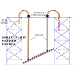
•Interference with the structures already in position, require that during part of the lifting the drum is in an inclined position.
Drum lifting was in the earlier days done using winches and pulley blocks. As the unit sizes and drum weights increased, drum lifting using jacks became the preferred method.
Strand Jack.
Using Strand Jacks has become the convenient method of lifting a boiler drum all over the world. Multiple strands in two or more strand jacks slowly but surely lifts the drum to its position. This is a simple method to lift the heavy weight.
Except for the preparation phase, only one or two operators are required for lifting the drum. Multiple strand jacks offer redundancy, reliability and safety. Using Strand Jacks is easier to install than a winch system and less costly than using a very heavy crane.
The Strand Jack is located on temporary beams on top of the boiler structure above the final position of the drum. Two or four jacks are used based on the lifting arrangement. Lateral movements of the jacks are possible by mounting them on roller skids. This is necessary to maintain verticality and to avoid interference with the supporting structure.
Strands
The jacks itself uses multiple strands, 10 to 14 depending on the load and jack capacity. The lower ends of the strands connect to blocks that fix one end of the strands. The other end of the strands is free and moves through the jack. The blocks connect to the lifting lugs of the drum by links or grommets.
The strands are made of high strength special steels.
Lifting
The lifting operation takes around 8 to 12 hours. The drum lifts off directly from the transportation vehicle. Lifting the drum at an incline is necessary to avoid interference with the supporting structures.The multiple jacks can operate in synchronization or separately. This allows for safe lifting evn if the drum is at an incline. Once it reaches the final position the permenant supports are installed.
The attached figures show the steps in a typical boiler drum installation.
The multiple strands and the positive locking method of the jacks give redundancy, reliability and safety for the entire operation.
Images


Using Hydraulic Jacks for Heavy Lifting.
Hydraulic Jacks offer very high mechanical advantage. Special Hydraulic jacks are in use to lift heavy loads. Many times these are alternatives to cranes for lifting and positioning heavy weights. This article series explains some of the applications.
Read Full Post | Make a Comment ( None so far )« Previous Entries
